how to make Smart Blind Stick Using Microcontroller AT89s52?
For More updates about coming Project guides please join our Telegram channel - http://t.me/Edupdf1
And Keep an eye on http://edupdf.xyz

INTRODUCTION
A Blind person needs to know the obstacle or anything that is in there way. Traditionally they uses a simple stick to sense the front things. Visually impaired persons have difficulty to interact and feel their environment. They have little contact with surrounding. Physical movement is a challenge for visually impaired persons, because it can become tricky to distinguish where he is, and how to get where he wants to go from one place to another. To navigate unknown places he will bring a sighted family member or his friend for support. Over half of the legally blind people in the world are unemployed. Because limited on the types of jobs they can do. They have a less percentage of employment. They are relying on their families for mobility and financial support. Their mobility opposes them from interacting with people and social activities. In the past different systems are designed with limitations without a solid understanding of the non-visual perception. Some of the systems are only for indoor navigations, and has no hurdle detection and determining location feature in outdoor environment. Researchers have spent the decades to develop an intelligent and smart stick to assist and alert visually impaired persons from obstacles and give information about their location Over the last decades, research has been conducted for new devices to design a good and reliable system for visually impaired persons to detect obstacles and warn them at danger places. There are some systems which has some deficiencies.
We have made the smary blind stick using microcontroller. We have used ultrasonic and IR sensor as distance measuring Unit. And we are using very basic push button logic with foil for water sensor. To analys the input we have taken AT89S52 and to give output as Audio we are using APR33A3 and speaker. Since there is only one option to tell a visually disabled person about their path.
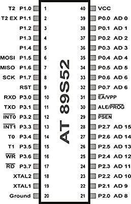
1. AT89S52
A microcontroller is a compact integrated circuit designed to govern a specific operation in an embedded system. A typical microcontroller includes a processor, memory and input/output (I/O) peripherals on a single chip.
Sometimes referred to as an embedded controller or microcontroller unit (MCU), microcontrollers are found in vehicles, robots, office machines, medical devices, mobile radio transceivers, vending machines and home appliances among other devices.
A microcontroller's processor will vary by application. Options range from the simple 4-bit, 8-bit or 16-bit processors to more complex 32-bit or 64-bit processors. In terms of memory, microcontrollers can use random access memory (RAM), flash memory, EPROM or EEPROM. Generally, microcontrollers are designed to be readily usable without additional computing components because they are designed with sufficient onboard memory as well as offering pins for general I/O operations, so they can directly interface with sensors and other components.
The AT89S52 is a low-power, high-performance CMOS 8-bit microcontroller with 8K bytes of in-system programmable Flash memory. The device is manufactured using Atmel’s high-density nonvolatile memory technology and is compatible with the industry-standard 80C51 instruction set and pinout. The on-chip Flash allows the program memory to be reprogrammed in-system or by a conventional nonvolatile memory programmer. By combining a versatile 8-bit CPU with in-system programmable Flash on a monolithic chip, the Atmel AT89S52 is a powerful microcontroller which provides a highly-flexible and cost-effective solution to many embedded control applications. The AT89S52 provides the following standard features: 8K bytes of Flash, 256 bytes of RAM, 32 I/O lines, Watchdog timer, two data pointers, three 16-bit timer/counters, a six-vector two-level interrupt architecture, a full duplex serial port, on-chip oscillator, and clock circuitry. In addition, the AT89S52 is designed with static logic for operation down to zero frequency and supports two software selectable power saving modes. The Idle Mode stops the CPU while allowing the RAM, timer/counters, serial port, and interrupt system to continue functioning. The Power-down mode saves the RAM contents but freezes the oscillator, disabling all other chip functions until the next interrupt or hardware reset.
2. ULTRASONIC SENSOR (HC SR-04)
The Ultrasonic sensor module is a convenient way for measuring distances from objects. This module has a lot of applications such as parking sensors, obstacle and terrain monitoring systems, industrial distance measurements, etc. It has a stable performance and high accuracy ranging from 2cm to 450cm with a resolution of 0.3 cm. The module sends an ultrasonic signal, eight pulses of 40kHz square wave from the transmitter; the echo is then picked up by the receiver and outputs a waveform with a time period proportional to the distance. The connected microcontroller accepts the signal and performs necessary processing.


the timing diagram, you can see that the 40KHz pulse train is transmitted just after the 10uS triggering pulse and the echo output is obtained after some more time. The next triggering pulse can be given only after the echo is faded away and this time period is called cycle period. The cycle period for HC-SR04 must not be below 50mS. According to datasheet, the distance can be calculated from the echo pulse width using the following equations.
Distance in cm = echo pulse width in µS/58
Distance in inch = echo pulse width in µS/148
1. IR module
An infrared sensor is an electronic device, that emits in order to sense some aspects of the surroundings. An IR sensor can measure the heat of an object as well as detects the motion. These types of sensors measures only infrared radiation, rather than emitting it that is called as a passive IR sensor. Usually in the infrared spectrum, all the objects radiate some form of thermal radiations. These types of radiations are invisible to our eyes, that can be detected by an infrared sensor. The emitter is simply an IR LED (Light Emitting Diode) and the detector is simply an IR photodiode which is sensitive to IR light of the same wavelength as that emitted by the IR LED. When IR light falls on the photodiode, The resistances and these output voltages, change in proportion to the magnitude of the IR light received.
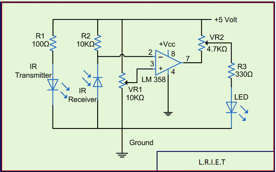
An infrared sensor circuit is one of the basic and popular sensor module in an electronic device. This sensor is analogous to human’s visionary senses, which can be used to detect obstacles and it is one of the common applications in real time. This circuit comprises of the following components
· LM358 IC 2 IR transmitter and receiver pair
· Resistors of the range of kilo ohms.
· Variable resistors.
· LED (Light Emitting Diode).
In this project, the transmitter section includes an IR sensor, which transmits continuous IR rays to be received by an IR receiver module. An IR output terminal of the receiver varies depending upon its receiving of IR rays. Since this variation cannot be analyzed as such, therefore this output can be fed to a comparator circuit. Here an operational amplifier (op-amp) of LM358 is used as comparator circuit.
When the IR receiver does not receive a signal, the potential at the inverting input goes higher than that non-inverting input of the comparator IC (LM358). Thus the output of the comparator goes low, but the LED does not glow. When the IR receiver module receives signal to the potential at the inverting input goes low. Thus the output of the comparator (LM358) goes high and the LED starts glowing. Resistor R1 (100 ), R2 (10k ) and R3 (330) are used to ensure that minimum 10 mA current passes through the IR LED Devices like Photodiode and normal LEDs respectively. Resistor VR2 (preset=5k ) is used to adjust the output terminals. Resistor VR1 (preset=10k) is used to set the sensitivity of the circuit Diagram.
1. APR33A3 (Audio module)
Today’s consumers demand the best in audio/voice. They want crystal-clear sound wherever they are in whatever format they want to use. APLUS delivers the technology to enhance a listener’s audio/voice experience. The aPR33A series are powerful audio processor along with high performance audio analog-to-digital converters (ADCs) and digital-to-analog converters (DACs). The aPR33A series are a fully integrated solution offering high performance and unparalleled integration with analog input, digital processing and analog output functionality. The aPR33A series incorporates all the functionality required to perform demanding audio/voice applications. High quality audio/voice systems with lower bill-of-material costs can be implemented with the aPR33A series because of its integrated analog data converters and full suite of quality-enhancing features such as sample-rate convertor. The aPR33A series C2.0 is specially designed for simple key trigger, user can record and playback the message averagely for 1, 2, 4 or 8 voice message(s) by switch, It is suitable in simple interface or need to limit the length of single message, e.g. toys, leave messages system, answering machine etc. Meanwhile, this mode provides the power-management system. Users can let the chip enter power-down mode when unused. It can effectively reduce electric current consuming to 15uA and increase the using time in any projects powered by batteries
Block Diagram

Circuit diagram

WORKING
Water sensing – it just a open circuit joined to an input pin when water will flow between two foiled sheets , circuit will be closed and pin will become high and Microcontroller gives output to relay
Depth sensing – if the IRD (depth measuring IR) does not detects anything then Microcontroller gives High out to relay.
wall sensing – if the IRD (depth measuring IR) does not detects anything then Microcontroller gives High out to relay.
Small object – if ultrasonic sensor gives value of distance less predetermined value then Microcontroller gives output to buzzer unit.
Audio module Input – audio i.e. APR33A3 needs grounding trigger to give respective output so to give that we have connected common port of relay to APR input and the normally off pin to ground so if the relay gets triggered then the APR33a3 gets trigger.
Addition point –
· Stick must be steady so that we can get right values for depth and horizontal sensors and hence we have connected push button at the bottom of the stick, so when the stick is placed on the surface and push button will be pressed and then and only then program runs.
· We need 5V to give input to Microcontroller but IR does not gives complete 5V connection that’s there is need of Relay circuit
Flow chart

ADVANTAGE AND DISADVANTAGE
Advantages –
1. It provides Artificial to Blind people
2. It detects water on surface
3. Gives different output for different Situation
4. Output can be in normal language so it is easy to understand
Disadvantages –
1. Metal surface will detected as water
2. Only one output will given by APR33A3
3. Adds little weight to traditional blind stick


How to program microcontroller IC? - https://edupdf.xyz/how-to-program-an-microcontroller-ic/
ReplyDelete